Overview
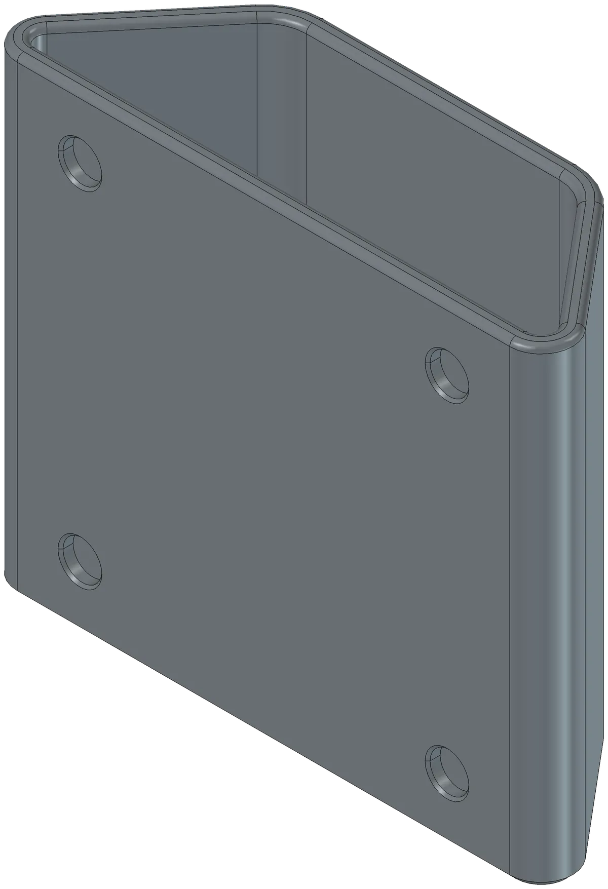
This collection contains editable FreeCAD designs for useful printed parts. The Fridge Cup is a small example: an open-topped holder that mounts to a ferrous surface with four magnets in its back.
The project keeps the source model, print-ready export, drawing, and physical observations together. That makes it possible to adapt the design to a different space or set of magnets without treating the original mesh as the only available starting point.
Model dimensions
The Fridge Cup exposes its dimensions through a FreeCAD VarSet.
| Parameter | Default | What it controls |
|---|---|---|
| Length | 100 mm | Outer footprint length |
| Width | 30 mm | Outer footprint width |
| Depth | 75 mm | Cup height |
| Thickness | 3 mm | Wall thickness |
| Fillet | 5 mm | Vertical corner radius |
| MagDiameter | 6.2 mm | Magnet pocket diameter |
| MagThickness | 2 mm | Magnet pocket depth |
| MagInset | 10 mm | Pocket inset from the corners |
| Angle | 60° | Trapezoidal base angle |
The top edge uses twice the main fillet value. The magnet pockets are part of the model rather than an annotation added after export.
Editing the model
Open the .FCStd source and select the VarSet in the model tree. Adjust the dimensions there, recompute, and inspect the resulting geometry before exporting a new print file.
Useful checks for a revision include:
- Overall size changes independently from wall thickness.
- Magnet dimensions match the purchased components.
- Pocket placement still leaves enough material around the edges.
- Fillets remain valid after changing the footprint.
- The editable source is saved alongside the new export.
Exposing a parameter makes a change easier to find. It does not guarantee that every possible combination produces valid or printable geometry.
Printing and assembly
The intended orientation is the closed base on the build plate, with the opening facing upward. The project notes describe that orientation as avoiding supports.
The original mounting uses four 6 × 2 mm neodymium discs pressed into the rear pockets. The 6.2 mm modeled diameter provides the documented pocket size; actual fit still depends on the print and the magnets.
The .3mf export is available for slicing, while the source remains the place to change the design.
Physical result and limitation
The original small magnets only just supported two full-size dry-erase markers without slipping. This observation belongs with the geometry because it identifies a real constraint for the next revision.
For a heavier load, the project’s notes suggest revisiting magnet diameter, depth, and strength. Changing those dimensions is straightforward in the model, but a revised mount still needs to be checked physically.
This is more useful than calling the part universally finished: the shape works as a holder, while the mounting performance depends on its load and hardware.
Files and related builds
The FreeCAD repository contains the source, 3MF, drawing, and license. Retain the attribution and license with redistributed versions.
Other examples of fitting printed geometry to real objects include the Catan organizers and the electric bicycle mounts. Each project has its own fit and assembly constraints.