Overview
This bicycle conversion combines a custom belt drive with frame-mounted electronics and an ESP32 display. The project archive keeps the digital assembly, printable parts, firmware, and photographs of the finished bicycle together.
It is a useful example of three kinds of work meeting in one object: the drive has to fit mechanically, the electronics have to communicate, and the dashboard has to make their measurements readable while attached to the bike.
Mechanical assembly
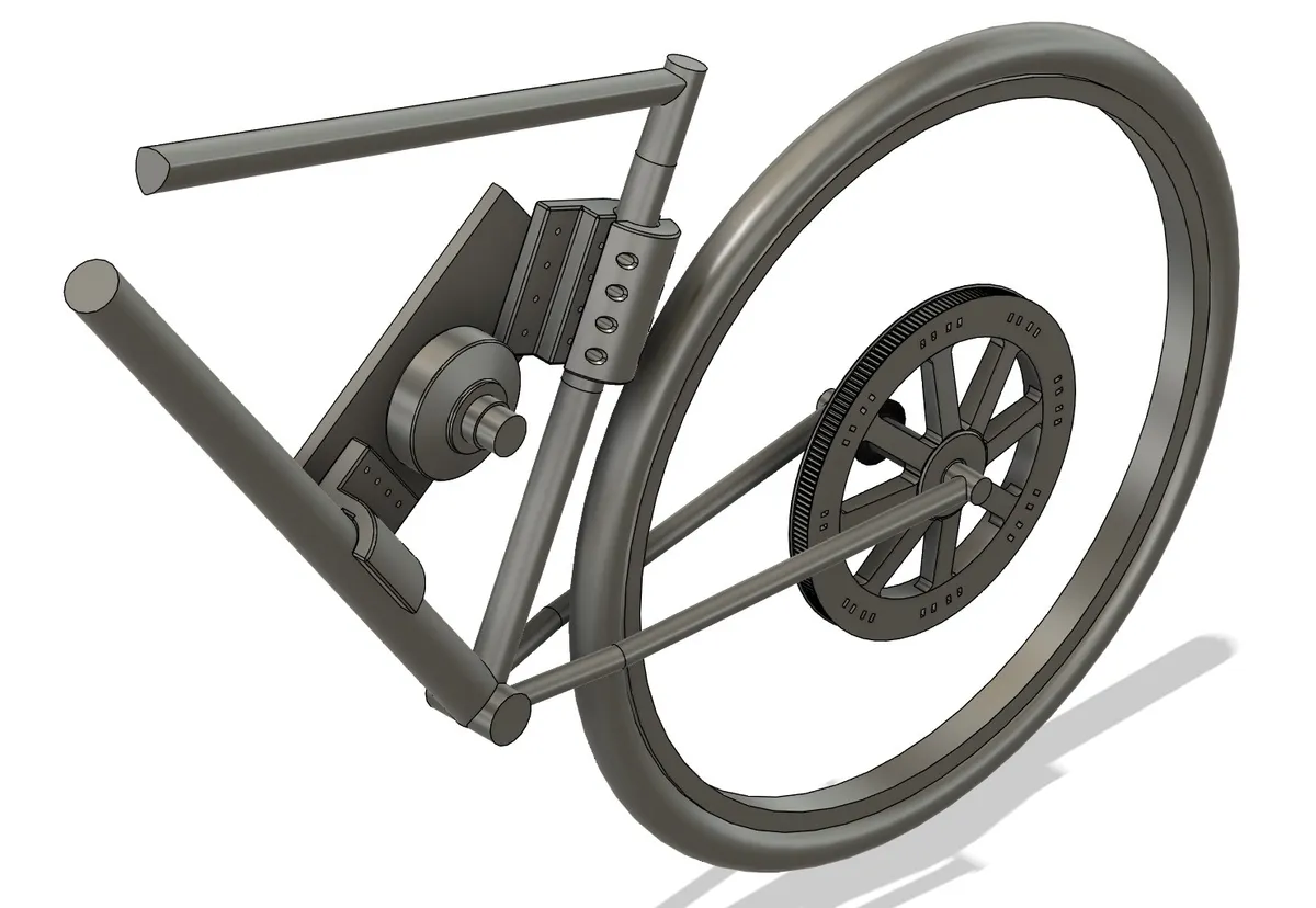
The CAD archive includes the bicycle frame, wheel, motor, pulleys, and mounting geometry. A Fusion 360 assembly records their relationship rather than treating each printable part as an isolated object.
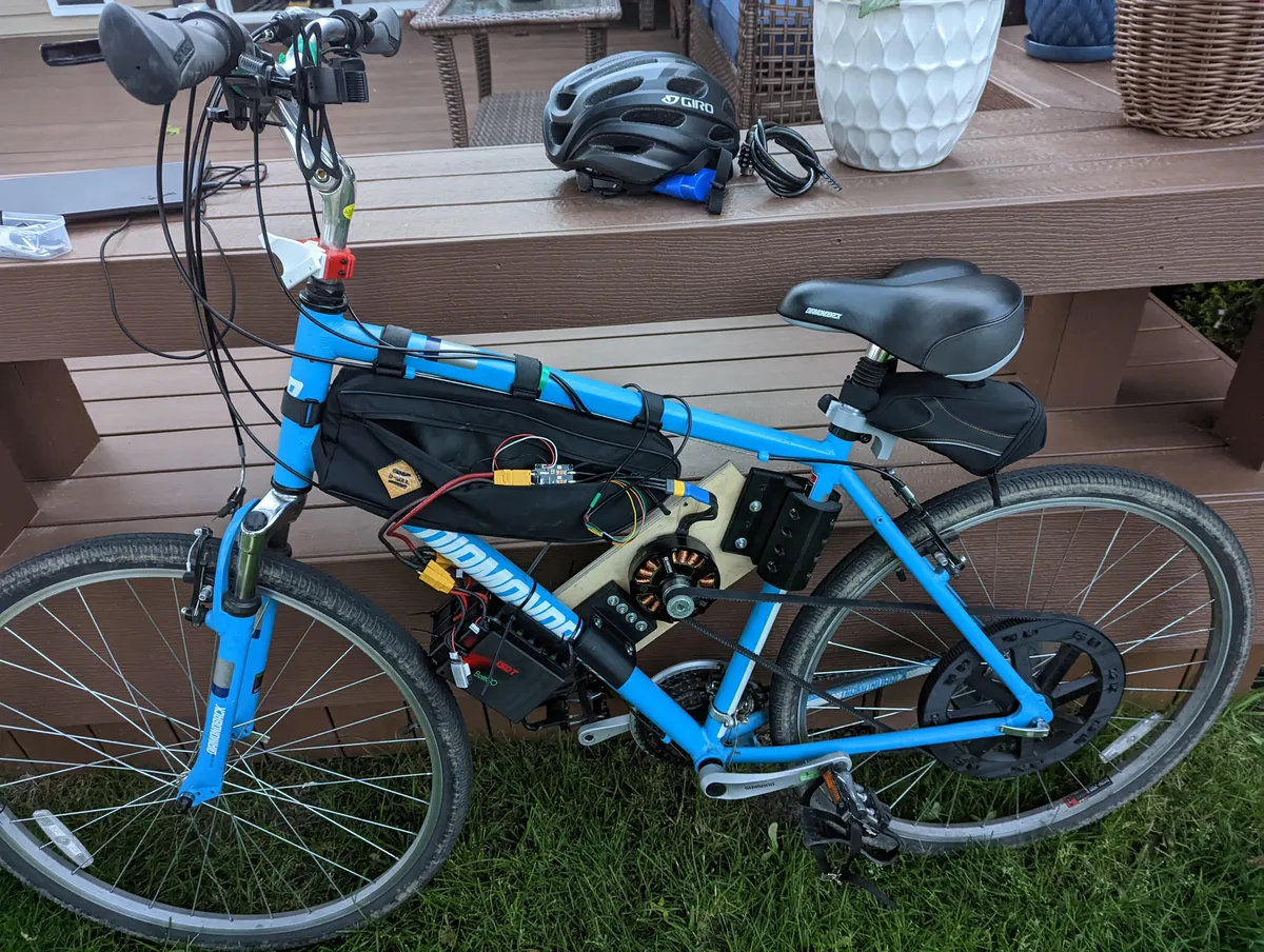
The exported parts include a motor mount, rear pulley, and two seat-tube clamp halves. The assembly photographs show how the motor, large rear pulley, belt, and frame-mounted components fit on the actual bicycle.
The source files retain separate component models, including a 180-tooth pulley revision. Their names preserve the design history; an exported mesh alone would lose much of that editable structure.
Electronics and telemetry
An ESP32 communicates with the VESC motor controller over UART. The display sketch uses the VescUart library for controller data, TFT_eSPI for the screen, and FastLED for addressable lighting.
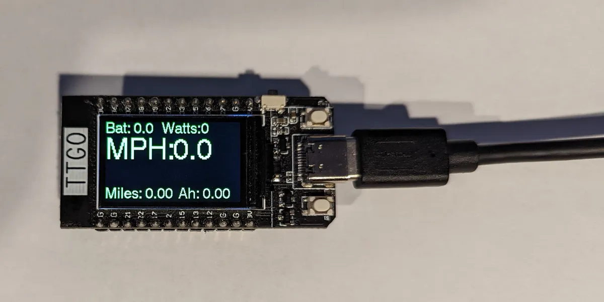
The display presents battery voltage, estimated electrical power, speed, distance, and amp-hours. Power is calculated from input voltage and current. Speed and distance are calculated from controller RPM and tachometer readings using constants in the sketch.
The lighting code also cycles colors on an eleven-pixel WS2812 strip. That behavior is part of the same prototype firmware, alongside the dashboard drawing and telemetry polling.
Dashboard implementation notes
The archived sketch initializes the controller serial connection at 115,200 baud and updates selected regions of the TFT rather than rebuilding the whole screen as one image.
The telemetry conversions are specific to this build. Motor pole count, wheel diameter, and pulley ratio affect the meaning of the reported RPM and distance. The code includes hard-coded conversion factors, and some nearby comments describe different example values. Those constants need to be checked against the actual drivetrain before reusing the sketch.
A photograph of a working screen demonstrates the interface. It is not a separate calibration record for the speed or distance estimate.
Files and build record
| Folder | Contents |
|---|---|
CAD/Fusion360 |
Editable component files and the assembly archive |
CAD/STL |
Motor mount, rear pulley, and seat-tube clamp exports |
Code/VESCOM |
Dashboard sketch and display assets |
Pictures |
Assembled bike, CAD assembly, pulley, and dashboard photographs |
The public build repository is the source for these files. The build photos below connect the digital models to the fabricated parts.
Status and reuse
This is a completed personal hardware build with an archived prototype dashboard. The available material documents what was assembled and how the display code works; it does not establish a tested range, maximum speed, or a universal conversion kit.
For a different bicycle, the frame fit, drivetrain geometry, mounting loads, and telemetry constants become a new integration problem. The editable CAD is the useful starting point.
Build photos