Overview Link to section: Overview
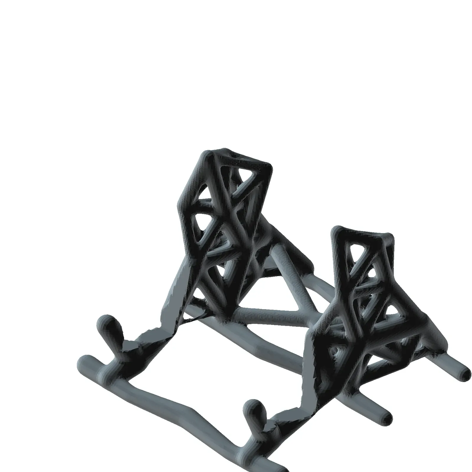
I designed this one-piece guitar floor stand in FreeCAD (open-source CAD, or computer-aided design, software) around a stable 3D ground structure (a network of candidate load paths). Twelve sizing iterations redistribute rib area for vertical, rearward, and both lateral loads. Gaussian field blending (smoothly merging overlapping mathematical fields) joins those paths into a continuous organic skin and carves out the padded guitar envelope (the space reserved for the instrument and its padding).
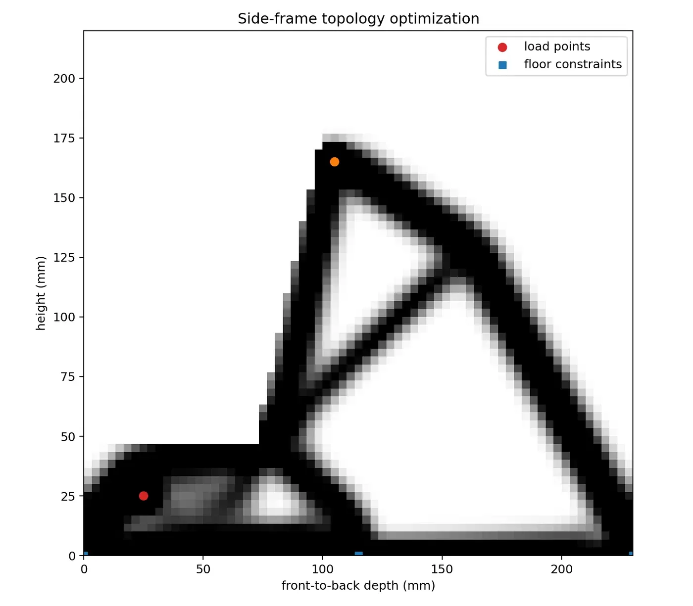
The cover is a CAD render. The gallery preserves an earlier 2D SIMP (Solid Isotropic Material with Penalization, a topology optimization method that redistributes material under loads) study from topology-side.png. My current model instead uses a 3D force-sized cellular generator in make_guitar_stand.py.
Build details Link to section: Build details
I sized the stand for a 45 mm guitar body with a minimum 51 mm padded envelope, allowing 3 mm of padding per face. The footprint is 234 × 234 mm and the height is 181 mm. A 59 mm modeling keep-out (space excluded from the stand geometry) contains the required 51 mm padded envelope at a 12° lean.
The editable dimensions live on the Parameters object (the model’s named dimension controls). I can run make_guitar_stand.py through FreeCADCmd (FreeCAD’s command-line program) to regenerate the FCStd (editable FreeCAD document) and STL (triangle-mesh print file). The high-resolution STL is watertight, and the FreeCAD document also contains a hidden faceted solid for STEP (a solid CAD exchange format) export and analysis.
Print plan Link to section: Print plan
My documented starting plan is to print upright with the 234 × 234 mm base on the bed, using organic/tree supports (branching temporary structures) from the build plate beneath the steepest blended branches. It calls for PETG (polyethylene terephthalate glycol) or ASA (acrylonitrile styrene acrylate), both plastics used for 3D printing, with five walls, five top and bottom layers, and 25% gyroid infill (a repeating curved internal structure).
I specify 3–7 mm adhesive felt or closed-cell EVA (ethylene-vinyl acetate foam) on the seats, front lips, and backrest contact areas, trimmed for a stable fit. The modeled padding allowance is 3 mm per face, so the actual padding and guitar fit need checking together.
The first physical test should be low over a rug. The stand should not be used where children, pets, or foot traffic could knock the guitar sideways.
Simulation and limits Link to section: Simulation and limits
The print skin has 101,136 facets (about 101,000 mesh faces), with a solid volume of 583,956 mm³—about 31% below my previous blob-frame version. My FEA (finite element analysis, a calculation of structural response) design check uses CalculiX (a structural simulation solver) with 213,969 tetrahedral elements (small four-sided volume cells).
The calculation assumes solid isotropic PETG (the same material properties in every direction) with a 2 GPa elastic modulus (stiffness) and a fixed floor. It applies 150 N downward together with 50 N rearward and 50 N lateral loads. Maximum displacement is 0.813 mm; maximum von Mises stress (a combined measure of stress) is 7.58 MPa, giving roughly 2.6× margin against the specified 20 MPa printed-part design allowable.
These results are a design check, not certification of layer adhesion or knock-over resistance. A physical print still needs testing low over a rug before trusting it with an instrument.
Files and related builds Link to section: Files and related builds
The Guitar Floor Stand folder contains the editable source, generator, exports, and documented print and simulation notes. My Parametric FreeCAD Designs entry covers other editable parts in the same repository.
Build photos