Overview Link to section: Overview
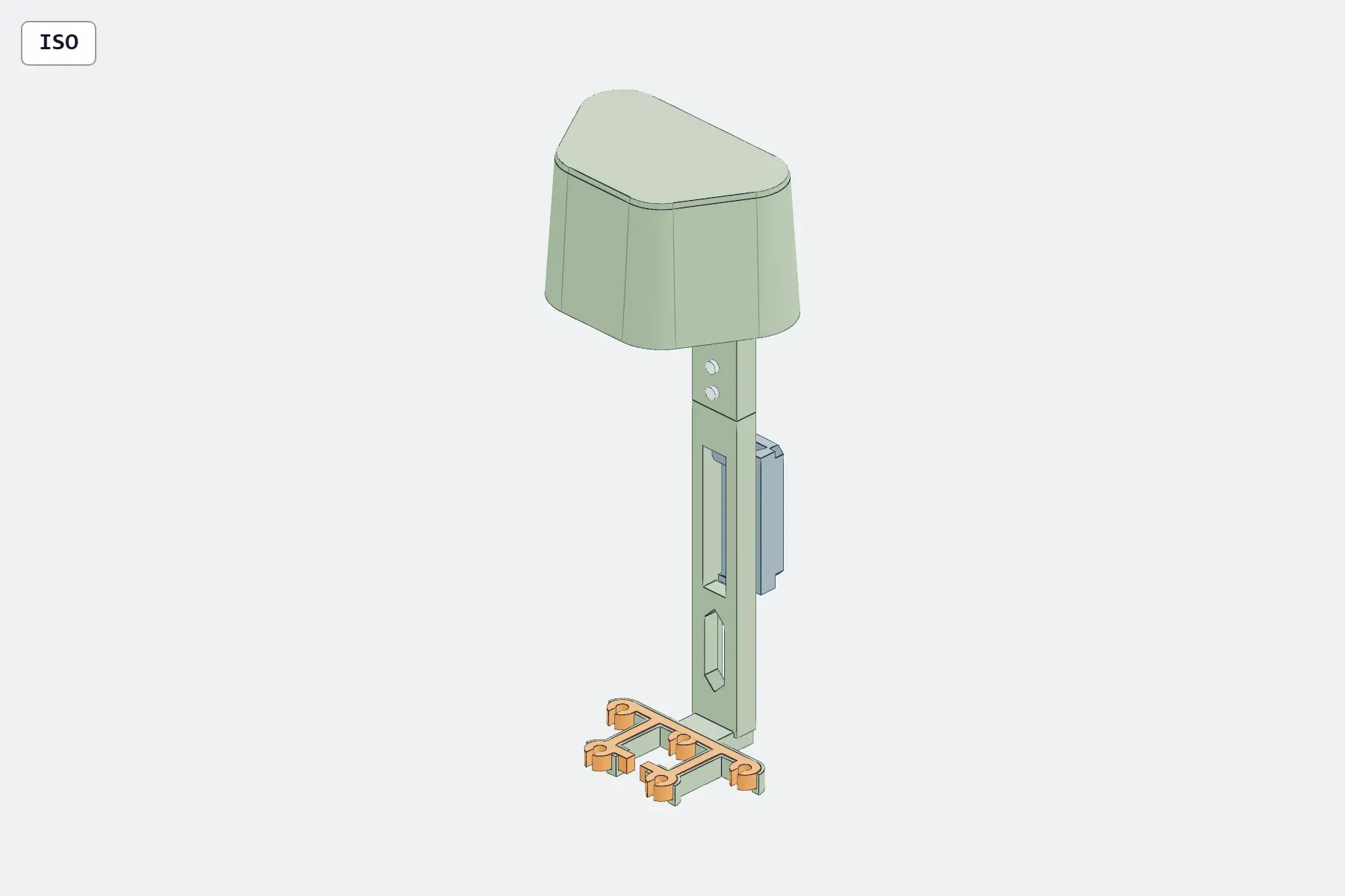
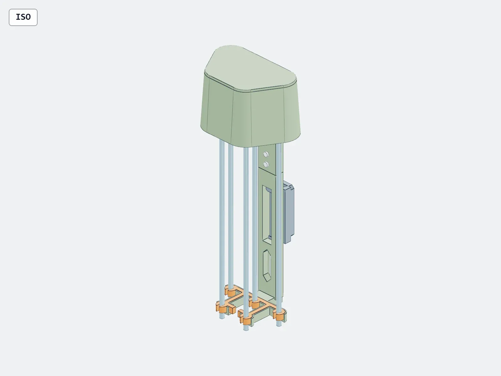
I designed this five-arrow quick-detach bow quiver for a left-hand Mathews LIFT X bow and Easton AXIS 340 arrows. The current V3 is a functional fit-test prototype in CAD (computer-aided design), with separate parts sized for the Bambu Lab A1, my intended 3D printer.
The assembled frame is approximately 360 mm tall. The images show modeled parts and reference arrows, not a physical build.
The arrow-trapping lesson Link to section: The arrow-trapping lesson
My earlier MountV2 revision had an open basket above closed shaft ports. Those ports trapped complete arrows: checking that a shaft hole was open did not establish that an arrow with a head could load and release. That revision is superseded and not functional.
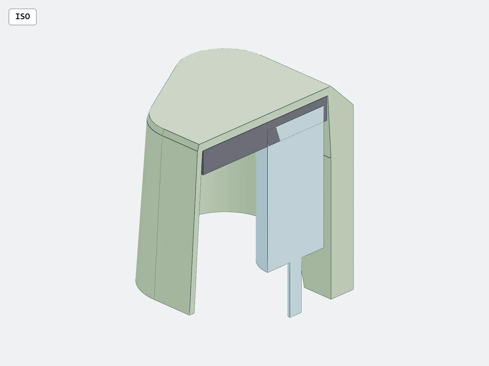
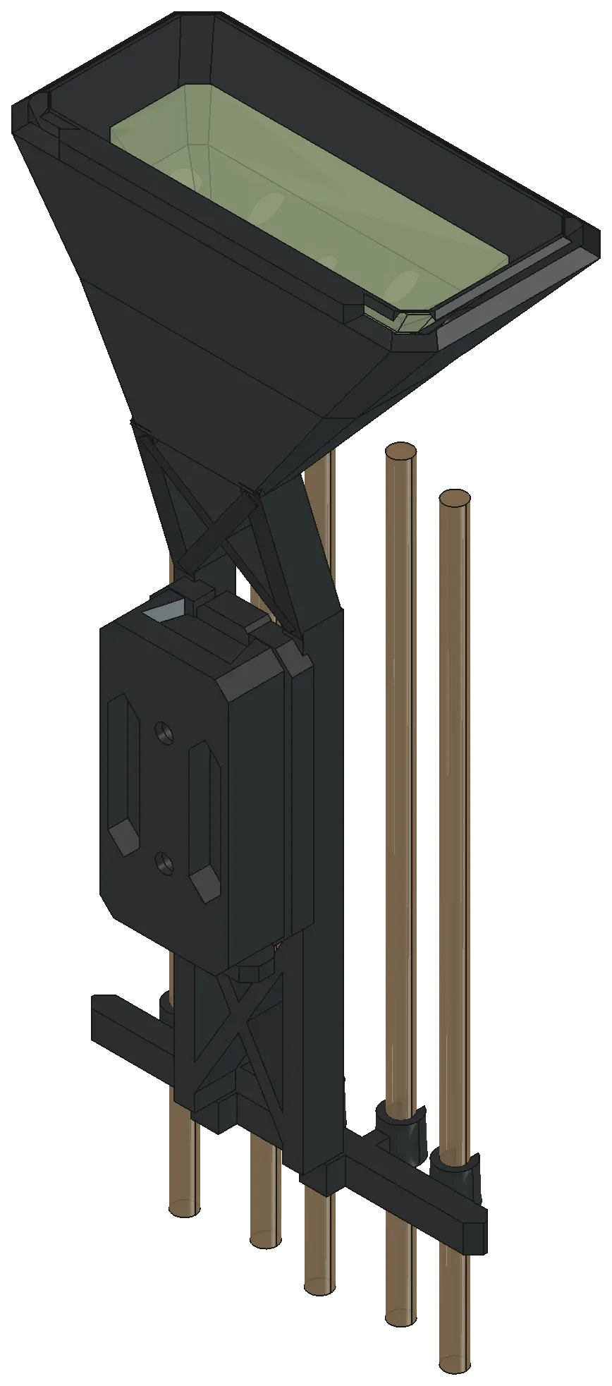
I rebuilt V3 around the complete arrow’s removal path. The enclosed broadhead hood has an open mouth facing down toward the grippers, with no floor or hard shaft hole to thread an arrow through. To remove an arrow, the shaft releases sideways from its gripper, then withdraws until the head clears the hood before moving outboard.
Frame, hood, and gripper Link to section: Frame, hood, and gripper
The frame splits into a hood/upper spine and a lower spine/carrier. A 34 mm tongue-and-socket overlap joins them with two M4 screws and nuts. The hood connects directly along the spine’s back wall, and a slide-off dock provides an exposed release.
I made the shaft gripper replaceable in TPU (a flexible plastic used for 3D printing). Its five side-entry jaws sit in open-front rigid saddles with room to flex. Seven variants cover the documented standard Easton AXIS spine sizes—600, 500, 400, 340, 300, 260, and 200. Spine here means the arrow’s stiffness rating, not the quiver’s frame.
The sizing coupon (a small fit-test print) has seven samples marked with recessed dots. For AXIS 340, my plan starts with the four-dot sample in the same TPU as the final gripper, checked against an actual bare shaft. The listed shaft outside diameter is 6.7818 mm; printed grip and release still depend on material and calibration.
The hood targets a stored broadhead envelope of at most 35 mm diameter by 70 mm length, including blades and ferrule. A 12 mm cut-foam template sits inside the cap; it represents replacement quiver foam, not a printed insert. Actual head fit, foam engagement, blade containment, and puncture protection remain untested.
Print plan Link to section: Print plan
I plan to print the sizing coupon first, then one lower frame, one upper hood, the selected AXIS 340 gripper, and the provisional dock. The starting material is PETG (a plastic used for rigid printed parts) for the frame and dock, and TPU 95A (a specified hardness grade) for the gripper.
My documented starting settings use a 0.4 mm nozzle and 0.20 mm layers, with five walls and 35% infill for the rigid parts. The hood prints cap-down, the lower frame with its carrier on the bed, and the dock with its bow-contact face down. Local holes, window bridges, and especially the dock’s release tongue need review in a slicer (software that prepares printer instructions), with removable supports where needed.
These are starting settings, not a validated printer profile. There is no successful slice or physical print documented. The assembly, reference arrows, foam template, and hardware models are not objects to print together.
Digital checks and remaining tests Link to section: Digital checks and remaining tests
My digital clearance checks sampled 85 positions for each of five complete-arrow removal paths, with the other four arrows stationary. The checked samples showed no overlap with hard parts or neighboring arrows, using cylindrical head envelopes. Foam and TPU contact were excluded, so this does not measure grip force or blade containment.
The files also include solid-geometry, mesh, build-volume, joint, and dock-slide checks, plus STEP (an exchange format for solid CAD models) import checks in FreeCAD. Earlier FEA (finite element analysis, a calculation of structural response) claims for MountV2 do not apply to the rebuilt V3 geometry.
Fit, retention, broadhead safety, joint strength, latch durability, and the bow interface have not been physically tested. The dock’s bow interface is provisional and is not a copy of Mathews’ LowPro geometry. I still need measured mounting geometry and checks for screw engagement, sight/rest/cable clearance, and the full draw cycle before considering installation or shooting. Initial off-bow trials should use blunt dummy heads or field points.
The V3 quiver folder contains the editable source, print exports, review renders, and test gates. My Parametric FreeCAD Designs entry covers other editable parts in the same repository.
Build photos