Overview Link to section: Overview
I built community examples and documentation for driving Seeed’s 6×10 RGB (red, green, and blue) WS2812 LED matrix from a XIAO nRF54L15. The project fills a gap for Zephyr (an embedded operating system) and nRF Connect SDK (Nordic’s software development kit) users, with C code, wiring notes, and patterns for the 60 individually controlled lights.
Getting the panel to light Link to section: Getting the panel to light
The stock worldsemi,ws2812-spi driver, which uses SPI (Serial Peripheral Interface) to generate the LED data signal, did not light this panel on this board. I built a GPIO (general-purpose input/output) bit-bang driver, which generates the signal by toggling a pin in software.
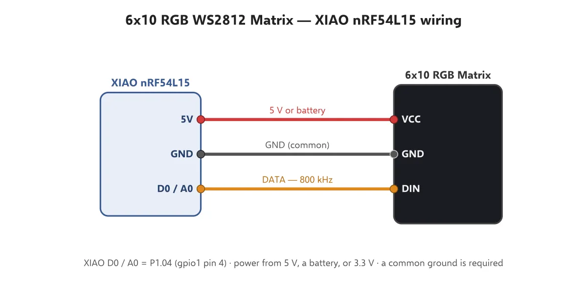
The data connection uses D0/A0, the XIAO header pin connected to P1.04 on the nRF54L15. My hardware notes and wiring diagram record that connection alongside the panel’s power and ground pins.
Finding the pixel order Link to section: Finding the pixel order
I reverse-engineered the pixel mapping by lighting pixels and observing their positions. The 6×10 panel has 10 runs of 6 pixels in plain raster order: each run follows the same direction. It is not serpentine (alternating direction on successive runs).
Documenting that observed order gives the demos a consistent way to translate positions on the panel into LED indices (numbers identifying individual lights).
Demo patterns Link to section: Demo patterns
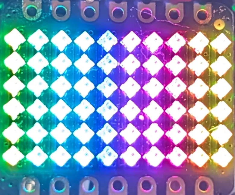
I included a demo gallery with a scrolling green dot, solid fills, a wipe, a rainbow, a bouncing dot, a breathing brightness pattern, and a 0–10 counter. These patterns exercise individual pixels, color changes, movement, and number display. The cover photo shows the panel running the rainbow demo.
Power and wiring Link to section: Power and wiring
I prefer 5 V for the panel’s VCC (power input), with a common ground between the panel and XIAO and D0/A0 connected to DIN (data input). The panel also works at 3.3 V, with dimmer output. The hardware notes collect the pinout and wiring details.
Related work Link to section: Related work
My nRF54L15 Support project provides reusable libraries and Zephyr drivers for the same microcontroller family. This matrix repository focuses on the Seeed panel’s driver, examples, and hardware documentation.
My Printed LED Sculptures are separate projects using printed structures and lighting; they are not builds of this matrix example.
Build photos