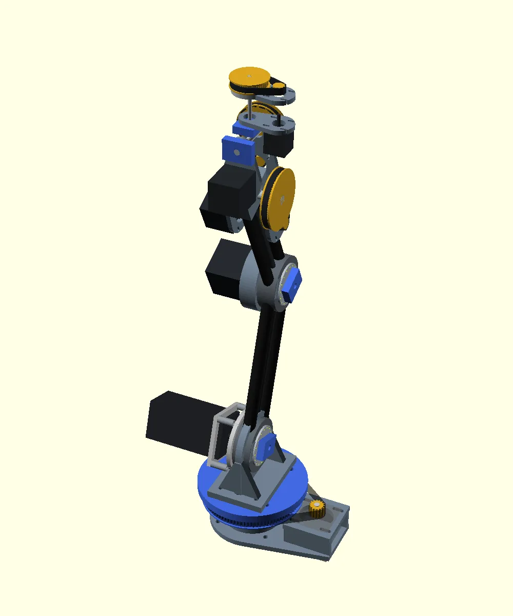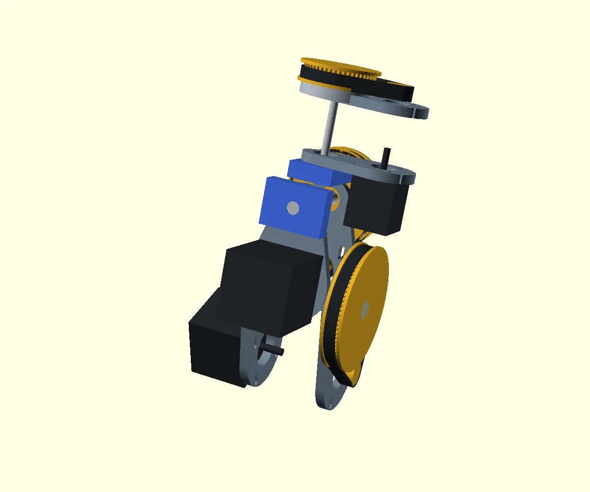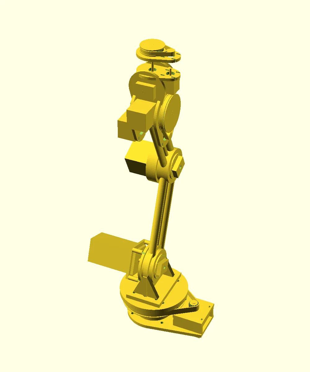
Overview Link to section: Overview
I designed this six-axis robot arm (an arm with six controlled joint motions) to tend a 3D-printing cell, a printer work area served by the robot.
The current revision, R3, is released as a first-article prototype package (the package for building and checking the first physical examples). It contains:
- A frozen requirement set.
- A printable structural parts set.
- A purchase list.
- A gate list: acceptance gates are checks that must pass before moving to the next stage, and these still require physical validation.
It is not approved for unattended operation, and no arm has been built yet.
Starting from the printer Link to section: Starting from the printer
I started the design work from the printer rather than from a generic robot. The arm has to reach into a Bambu A1 build volume (the space where the printer makes parts), pick printed parts, and stay inside the machine’s work zone.
Requirements Link to section: Requirements
The release freezes the numbers I hold the design to. Reach is the shoulder-to-tool distance; payload is the load carried by the arm, including its gripper and plate. Repeatability means returning to the same position across repeated moves.
| Requirement | Release target |
|---|---|
| Controlled axes | 6 |
| Shoulder-to-tool reach | 574 mm |
| Working payload | 0.50 kg including gripper and plate |
| Repeatability in the printer work zone | ≤1.0 mm after calibration |
| Full-workspace repeatability | ≤2.0 mm |
| Maximum tool speed during initial validation | 100 mm/s |
| Duty cycle during initial validation | 20% |
| Minimum continuous torque safety factor | 2.0 |
| Structural yield safety factor | 3.0 |
| Position feedback | Direct output encoder on every axis |
Duty cycle is the share of time spent operating. The torque and structural yield safety factors describe margins against the required turning force and permanent material deformation. An encoder is a sensor that measures joint position.
Mechanism Link to section: Mechanism
Joint drives and supports Link to section: Joint drives and supports
I paired each axis with a drive and a structural interface that can actually be manufactured. Yaw turns side to side, pitch tilts, and roll rotates the tool around its own axis. A harmonic reducer is a compact gear mechanism that reduces speed and increases turning force.
In the table, HTD-5M and HTD-3M identify toothed-belt profiles with 5 mm and 3 mm tooth spacing; T denotes tooth counts. ASA/PETG are printing plastics, PA-CF/PET-CF are carbon-fiber-filled nylon/polyester printing materials, and 6061-T6 is an aluminum alloy and temper.
| Axis | Mechanism | Structural interface |
|---|---|---|
| J1 yaw | 6:1 HTD-5M belt on two 6008 bearings | Printed ASA/PETG base on a steel bench plate |
| J2 shoulder | 50:1 harmonic reducer | 6 mm 6061-T6 fixed adapter |
| J3 elbow | 50:1 harmonic reducer | Printed PA-CF/PET-CF adapter |
| J4 pitch | 16T:80T HTD-3M belt | Printed wrist housing |
| J5 yaw | 16T:64T HTD-3M belt | Printed wrist housing |
| J6 roll | 16T:48T HTD-3M belt | Printed wrist housing |
Links, counterbalance, and feedback Link to section: Links, counterbalance, and feedback
The upper and forearm links are pairs of 18 × 1.5 mm and 16 × 1.5 mm carbon tubes clamped in printed end blocks.
The shoulder carries an 8 Nm gas-spring counterbalance (a spring that offsets part of the load) against a checked horizontal torque of about 14.3 Nm. Nm, or newton-metres, measures turning force. The J2 motor has an integrated power-off brake.
Every axis ends in a direct output encoder so position feedback comes from the joint rather than from the motor.
Manufacturing package Link to section: Manufacturing package
Model and exported parts Link to section: Model and exported parts
I generate the assembly from source using OpenSCAD, a code-based 3D modeling tool. cad/robot_arm_assembly.scad is the authoritative model. An export script produces the release set:
- Printable STLs (3D surface files) for the base, rotor, shoulder pedestal, elbow motor bell, wrist side plates, pulleys, tool flange (the tool mounting face), and both tube end-block sizes.
- DXF profiles (2D drawing files) for the aluminum plates.
I regenerate the export rather than storing it, so obsolete geometry cannot silently ship.
Inspecting before duplicating Link to section: Inspecting before duplicating
I deliberately staged the design around one purchased harmonic reducer. The release notes require buying and inspecting a single unit, then freezing the adapter pilot fits (locating surfaces) and bolt circle (bolt-hole arrangement) from the delivered part instead of nominal catalog dimensions.
The next step is producing one first-article part per geometry and recording bore sizes (hole diameters) and mass before duplicating anything.
Verification Link to section: Verification
Checks before a physical build Link to section: Checks before a physical build
The repository keeps the checks I can do before metal is cut: collision sweeps across joint angles (checking whether parts intersect as joints move), wrist kinematics views (showing joint motion), and an engineering check script over the assembly.
Hardware acceptance plan Link to section: Hardware acceptance plan
The acceptance plan still has to be run on real hardware. It includes:
- Reducer flange runout (wobble of the mounting face) under 0.10 mm.
- Encoder repeatability over 20 cycles.
- A static proof load of 1.0 kg for 60 seconds.
- A 30-minute thermal soak (sustained operation to check heating) at validation duty.
- An E-stop (emergency stop) test.
- The 30-approach repeatability test in the printer work zone.
Accuracy limits Link to section: Accuracy limits
My release is explicit that the 1 mm repeatability target is not proven by component specifications. The chosen encoders resolve about 0.22 mm per count (sensor increment) at full reach, and their specified absolute accuracy is worse than that.
Calibration can remove repeatable error, but the target is only accepted by the physical approach test.
Earlier concept Link to section: Earlier concept
The repository also holds my earlier R0 concept: a dual-arm cell built from a Bambu A1 mini and two low-cost arms. That concept includes:
- An E-stop and contactor interlock (an electrical switching arrangement that prevents operation when the interlock is open).
- A taught-pose state machine (control logic that moves through recorded arm positions).
- A documented budget.
That document is archived history and does not describe the active R3 design.
Current state Link to section: Current state
This is an engineering prototype. My design package, purchase notes, and validation gates are complete enough to order a staged first-article build, but nothing has been manufactured or measured. The repository is private.
Build photos